Sign up for our newsletter!
Your data will be handled in compliance with our privacy policy.
Your data will be handled in compliance with our privacy policy.

During the spring, we have had John Schack, a master’s thesis student, with us at Smoltek Hydrogen who has been working on the synthesis of carbon nanofibers (CNF) – where we have adjusted the growth recipe to use hydrogen as input instead of ammonia.
The project is now coming to its end – with promising results to present. Some main take-aways are:
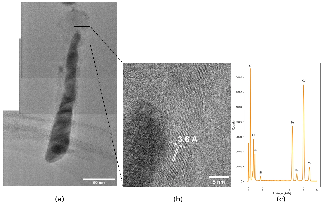
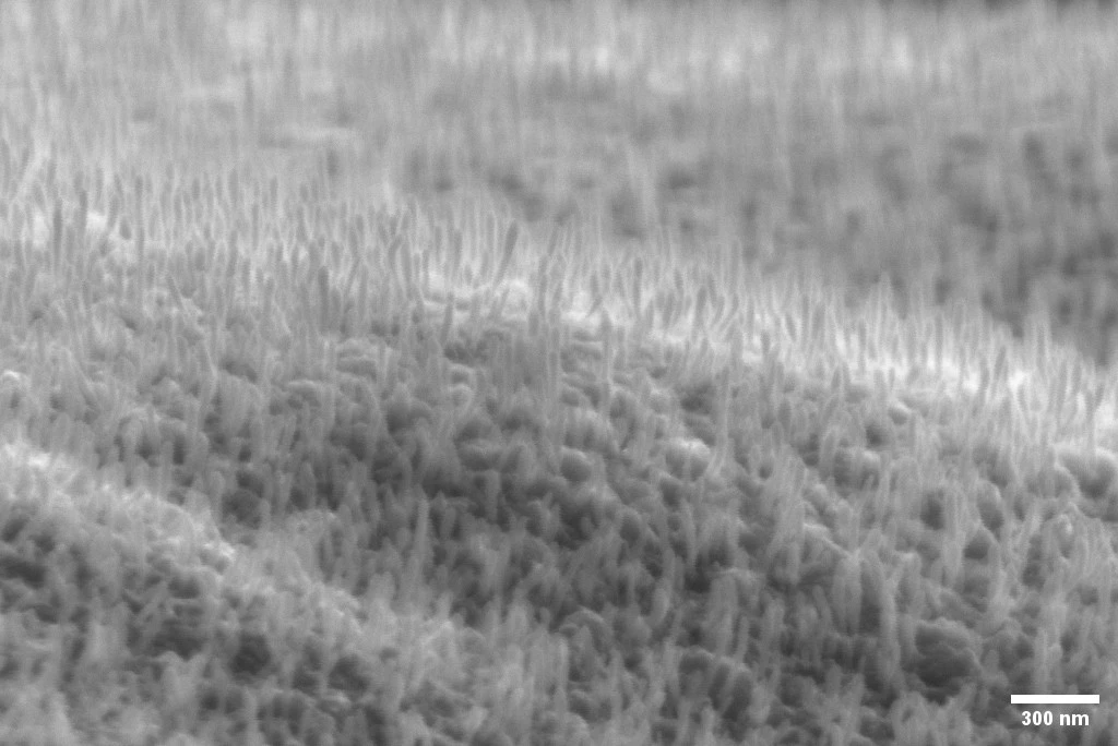
The growth of CNFs is a fascinating process and just like the green hydrogen production it requires a catalyst. Each fiber grows from a catalyst particle and usually the particle can be seen at the tip of the fiber, or at the base. By using a transmission electron microscope (TEM), capable of capturing details on the atomic scale, the grown fibers were imaged, and the result was rather unexpected: The catalyst particle in this case was elongated, almost along the whole fiber. The fibers could be called Fe-filled carbon nanotubes (CNT) or Fe/CNT core-shell fibers.
The behavior of the catalyst particle is intimately coupled to the growth and the observed shape is likely related to the issue with low growth rate – leading to plenty ideas of how to solve it. For example, exposing the substrate to a plasma treatment before CNF growth starts might loosen the catalyst particle from the substrate and change its behavior during growth. This type of core-shell structure is not only a problem to solve however, with the ferromagnetic properties of the Fe core it could prove interesting in its own right, perhaps for a future Smoltek business area?
In the near-term the possibility of using H2 in the process could lead to new ways of controlling the carbon nanofiber structure and increase flexibility when it comes to the planning of scale-up and commercialization. One potential up-side with the H2-based process is the production of free-standing CNFs which could improve water flow and gas bubble dissipation in the electrolysis cell but whether this can be realized with longer fibers remains to be seen.
If you are interested, please read more in the full thesis: Carbon nanofibers as catalyst support – Developing an H2-based recipe for plasma enhanced chemical vapor deposition.
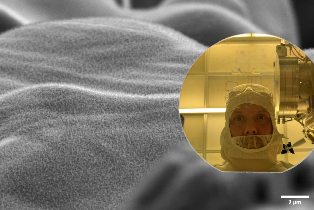
Top photo: Picturing a zoomed out view of grown carbon nanofibers and John Schack, a master’s thesis student at Smoltek Hydrogen, in the lab, reflected in a 6 inch wafer.
Your data will be handled in compliance with our privacy policy.
News

January 28, 2026
Smoltek Hydrogen, has been selected as one of nine Swedish cleantech companies to join the Swedish-German Cleantech Platform 2026. This strategic program, managed by the Swedish Energy Agency and the German-Swedish Chamber of Commerce, gives the opportunity to accelerate the company’s commercial expansion into Germany — Europe's leading and most dynamic market for green hydrogen and fuel cell technology.
News

November 20, 2025
We have launched a podcast about materials technology and investments in general and our disruptive carbon nanotechnology in particular.
News

November 4, 2025
Smoltek Hydrogen has received an order for samples of low iridium-load Porous Transport Electrodes (PTE) for PEM electrolyzers. The electrodes will be used in a joint development project with Heraeus Precious Metals, a global leader in precious metals.
News
October 30, 2025
Smoltek Hydrogen recently participated in the Hydrogen Technology World Expo 2025 in Hamburg, Germany – the world’s largest industry event for innovation in hydrogen and electrolysis technology. Ellinor Ehrnberg, President of Smoltek Hydrogen, was invited to a panel discussion on the topic “Overcoming the Key Obstacles in Electrolyzer Expansion”
News
June 12, 2025
Smoltek Hydrogen, has on behalf of a leading global automotive manufacturer completed successful tests of its nanostructure fuel cell electrodes.
News
June 12, 2025
Smoltek Hydrogen is developing Smoltek PTE – a proprietary porous transport electrode based on carbon nanostructures, which is intended to meet the requirements of next-generation PEM electrolyzers for the production of fossil-free hydrogen.